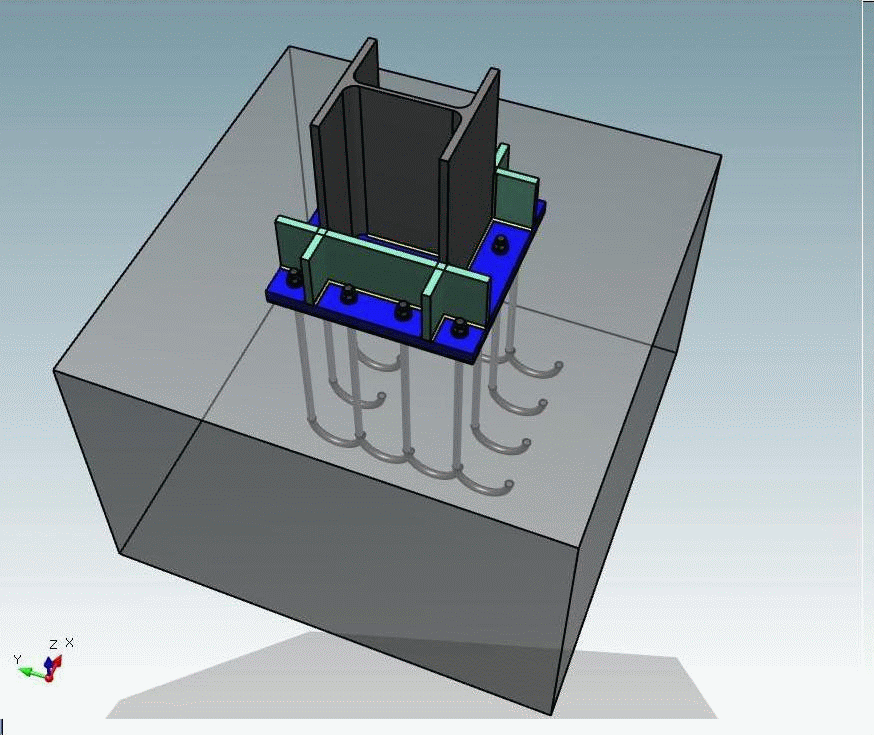
 This connection refers to a column-to-footing connection. The cross-section of the column can be either of I type or hollow. The connection is subjected to pure biaxial bending (not superposition of uniaxial bending). All types of anchors are supported (straight, with hook, with a nut, with square or rectangular anchorage plate). Apart from the anchors and the base plate the program also designs the footing, taking into consideration the soil parameters and the member forces. The user can also add stiffeners to increase the bearing capacity of the steel connection. All the components of the connection are checked according to EC3 while the program also produces the failure surface about the major and minor axis of the column.
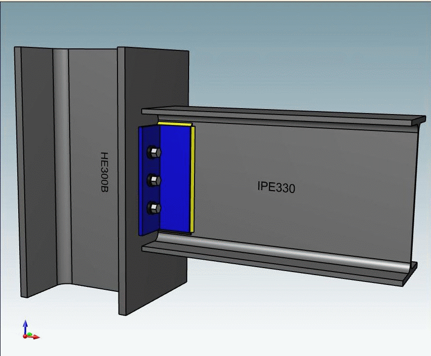 This connection refers to a beam-to-column shear connection through the use of two equal or unequal angle cleats. The cleats can be hot rolled or welded. The program performs all the relevant checks according to EC3 (bolts shear capacity, bolts bearing capacity, block shear capacity, bending and shear capacity of the angle cleats etc.).
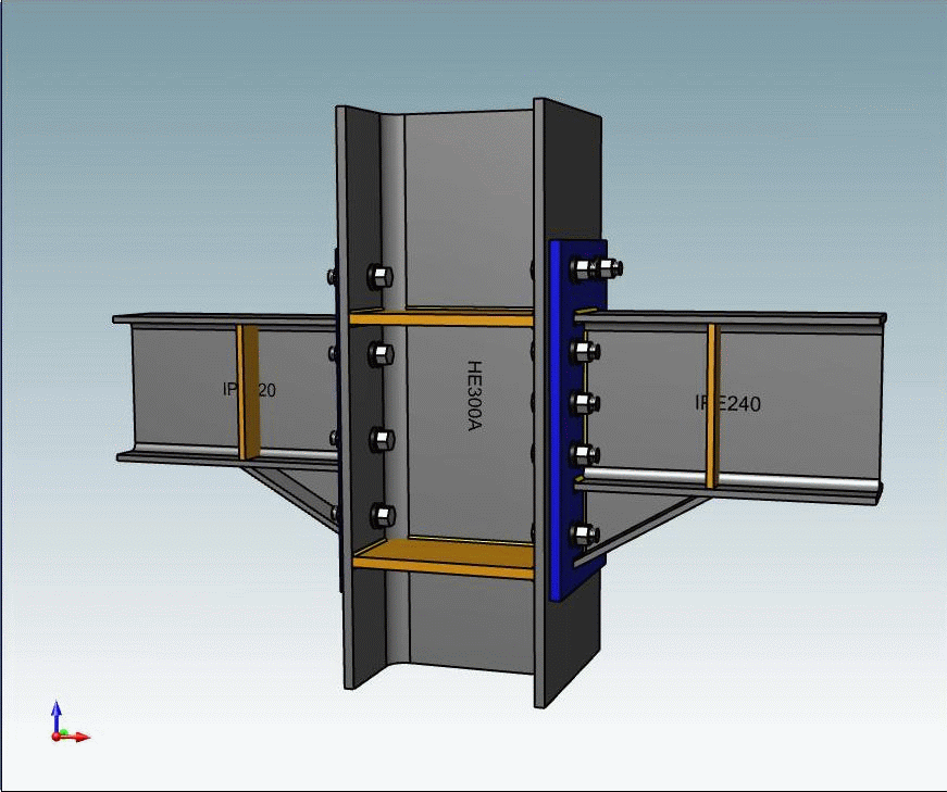 This type of connection can transfer bending moment from the beam to the column through the end plate. The user can design the connection with a beam either on one or both sides of the column, add beam and/or column stiffeners as well as haunches to increase the bearing capacity of the connection. All the components of the connection are checked according to Appendix 1-8 of Eurocode 3. The checks refer not only to the capacity of the connection elements but to the developed deformation of the connection (rotational capacity) as well.
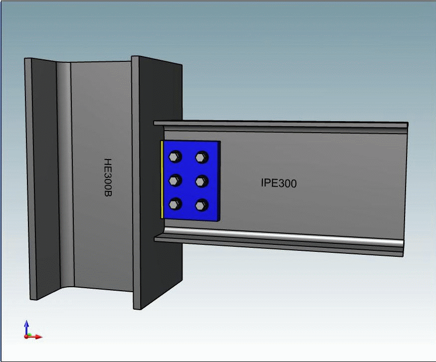 The beam is connected to the column through a rectangular steel plate which is welded to the column flange and the beam is then bolted to the plate. The cross-section of the column can be either of I type or hollow (RHS, SHS). The performed checks include: bolt shear capacity, bolt bearing capacity, block tearing for both beam and column, failure of the column face in case of hollow section.
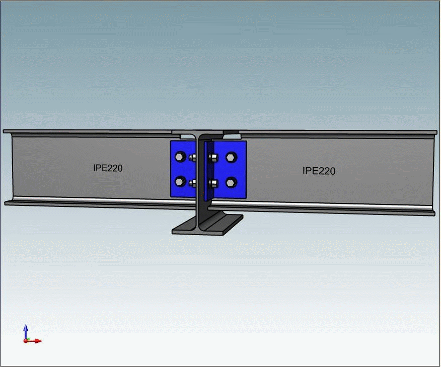 This connection refers to a secondary beam (supported beam) connected to the web of a main beam (supporting beam). The cross section of both beams must be of I type. Both equal and unequal double angle cleats can be used for the connection, either hot rolled or welded. The user can also define whether or not there will be a cut on the top or bottom flange of the secondary beam. The performed checks include: bending and shear capacity of the angle cleats, bolts shear and bearing capacity, block shear capacity for both beams. Moreover, the program checks if the connection meets the ductility criteria of Eurocode 3.
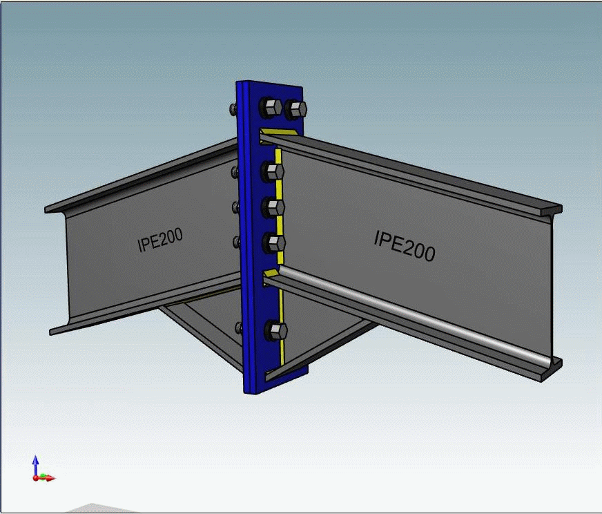 The connection refers to the splice of I-section beams through the use of end plates. All the components of the connection are checked according to Appendix 1-8 of Eurocode 3. The checks refer not only to the capacity of the connection elements but to the developed deformation of the connection (rotational capacity) as well.
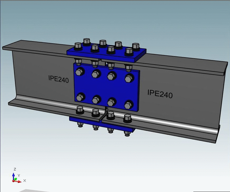 The connection refers to the splice of I-section beams through the use of steel plates. The steel plates can be attached to the web and flanges of the beams either with bolts or with a combination of welds and bolts. Besides the capacity of the connection elements, the program checks if the connection meets the ductility criteria of Eurocode 3, to ensure that brittle failure modes are avoided.
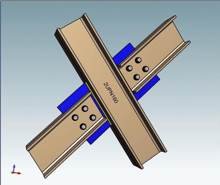 This connection type refers to Λ or X shaped bracings, covering a wide variety of connection geometry types. In case of X-shaped bracings the program offers the user the possibility to design the splice at the middle node. Additionally, apart from the usual checks, the user can perform capacity design of the bracing, assuming that the member in tension is ductile.